Engineering › Materials ›
Struts
An analysis of Struts using the EULER Formula.
Contents
Overview
By definition any member of a structure which is in Compression may be called a Strut. However, the term is usually reserved for long slender members which are likely to fail through buckling, rather than from compressive stress.As a structural member resisting longitudinal compression, a strut is commonly used in architecture and engineering. In relation to engineering applications, such as for automobiles and aeronautical structures, a strut can be used as a passive brace to reinforce the body, or as an active stress bearing component. As an example, lift struts (still used today on small light aeroplanes) are commonly employed to carry both tension and compression as the aircraft maneuvers in flight.

Description
The resistance of any member to bending is determined by it's flexural rigidity EI, but where, A is the cross sectional Area and k is the radius of gyration. So for a given material, the Load per unit area which a member can withstand is related to k. There will be two principal moments of Inertia and off these the least is taken. The Slenderness Ratio is given by : i.e The value of this ratio will determine whether a member falls into the category of Struts or Columns. Struts which fail by buckling before the limiting compressive stress is reached , can be analysed by the Euler Theory.Pin Ended Strut Axially Loaded.
It is assumed that the Strut is initially straight and that the compressive load is applied axially.
Example:
[imperial]
Example - Maximum Deflection of a strut in a strut testing machine
Problem
A straight Alloy bar 35 inches long and with a cross section of 1/2 and 3/16 inches, is mounted in a strut testing machine. It is loaded until it buckles. Assuming that the Euler Formula applies, estimate the maximum central deflection before the material attains it's yield point of 18 Tons/in2. E = 4690 Tons/in2.
Workings
There will be no deflection until the Euler load is reached. This load is given by:
The Maximum Bending Moment occurs at the centre where:
The Maximum Stress is the sum of Direct and Bending stress at the centre.
Solution
The maximum deflection  = 5.05
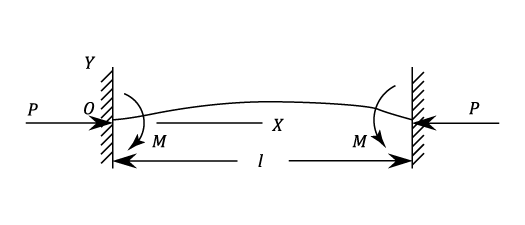
Direction Fixed At Both Ends

Partial Fixing Of The Ends
Example:
[imperial]
Example - Partial Fixing Of The Ends
Problem
A Strut of length 2a has each end fixed in an elastic material which exerts a restraining Moment  per unit of angular displacement. Prove that the critical Load P is given by the equation
  where
where  . Such a Strut 8ft. 4in. long has a critical load of 3,500 lbs. on the assumption that it is pin ended. Determine the percentage increase in the Critical Load is the constraints offered at the ends is 1,55 lb. in per degree of Rotation.
Workings
If M be the restraining Moment at both ends then
Using the notation given in the question.
At  ,
,  and
and  And
Thus
At the centre
  ,
,  i.e.
For pinned ends:
Substituting in equation (37)
The least solution of this equation is
  . This is an increase of 78% over the value for pin ended
Solution
This is an increase of 78% over the value for pin ended
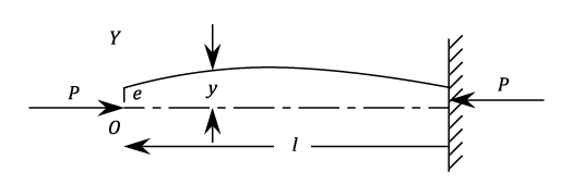
Strut With An Eccentric Load

Strut With Initial Curvature
These are treated as a beam with an initial radius of curvature such that:- Using Equation 10 "Bending of Curved Beams" Thus Under an end load P, the initial shape of the strutExample:
Example - Strut With Initial Curvature
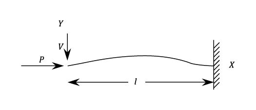
Problem
A Strut of length l is encased at it's lower end. The upper end is elastically supported against lateral deflection so that the resisting force is k times the end deflection. Show that the crippling load is given by:
where 
Workings
 Login
Login


