Built in Beams
The bending of Built in Beams fixed at both ends.
Introduction
A Beam is said to be Built-in or 'encastre' when both ends are rigidly fixed so that the slope remains horizontal - It is normal for both ends to be at the same level. In other words, it is assumed that built in beams have zero slope at each end, and therefore the total change of slope along the span is zero.
In general terms, all other geometrical aspects remaining the same, a built in beam is considered stronger than a simply supported beam . As built in beams are statically indeterminate, techniques such as linear superposition are often used to solve problems associated with them. The bending moment for a loaded built in beam is normally maximum at the end joints.
In this section we look at the Moment-Area method, and the Macaulay method (calculus method) to calculate the fixing moments and the end reaction.Moment-area Method For Built In Beams
It follows from the Moment-Area method (See Bending of Beams Part 3) that since the change of slope from end to end and the intercept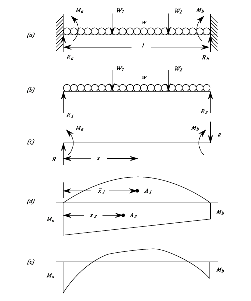
Due to  ,
,  and
and  the Bending Moment at a distance
  from the left-hand end is given by:
 This gives a straight line going from a value of
  at
at  to
to  at
at  . From this can be drawn the Fixing Moment Diagram
  (See d).
For the downward loads
(See d).
For the downward loads  is a positive area (Sagging
  ) and is a negative area (Hogging ). Consequently, equations (1) and (2) reduce to:
 And
And  (Numerically)
These give rise to two important statements:-
and to be found and the total reactions at the ends are :
(Numerically)
These give rise to two important statements:-
and to be found and the total reactions at the ends are :
 And
And  The Combined Bending Moment Diagram (e) is the Algebraic sum of the two components.
- Area of the Free Moment Diagram = Area of the Fixing Moment Diagram.
- The Moments of Areas of Free and Fixing Diagrams are equal.
Example:
[imperial]
Example - Example 1
Problem
Obtain expressions for the Maximum Bending Moment and deflection of a beam of length  and a flexural rigidity
  . The Beam is fixed horizontally at both ends ( built in) and carries a load
  which is:
- a) Concentrated at mid-span.
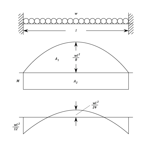
- b) Uniformly distributed over the whole beam.
Workings
- a) Concentrated Load

- b) Uniform Load
Solution
- a)
- b)
Macaulay Method
When the Bending Moment diagram does not lend itself to simplification into convenient areas, it may be quicker to use the calculus method (See Bending of Beams Part 3). This also has the advantage of giving the Fixing Moments and end Reactions directly, and enables the maximum deflection to be found.Example:
[imperial]
Example - Example 1
Problem
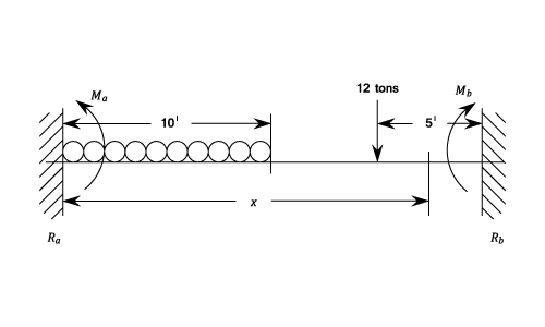
A Beam of uniform Section is built in at each end and has a span of 20 ft. It carries a uniformly distributed load of  on the left hand half together with a 12 ton load at 25 ft. from the left hand end.
Find the end reactions and Fixing Moments and the magnitude and position of the maximum deflection.
on the left hand half together with a 12 ton load at 25 ft. from the left hand end.
Find the end reactions and Fixing Moments and the magnitude and position of the maximum deflection.
Workings