Simple Supported Beams
Stress and deflection formulae for simple supported beams
Contents
- Introduction
- Simply Supported At Both Ends With A Uniform Load.
- Simply Supported At Both Ends . Load At Centre.
- Simply Supported At Both Ends. Load At Any Point.
- Simply Supported At Both Ends. Two Equal Loads Symmetrically Placed
- Simply Supported But With Both Ends Overhanging Symmetrically. Uniform Load.
- Simply Supported With Both Ends Overhanging, Supports Unsymmetrical, Uniform Load.
- Simply Unsymmetrically Supported With Both Ends Overhanging And A Load At Any Point.
- Simply Supported With Ends Overhanging. Single Overhanging Load.
- Page Comments
Introduction
The stress and deflection for simply supported beams under a number of loading scenarios is illustrated within this page. The following symbols have been used throughout:is the Stress at any point
is the Section Modulus of beam cross section.
is the deflection at any point.
is the load on the Beam. Note for uniform loads
where
is the load per unit length
is the Modulus of Elasticity ( Young's Modulus)
is the Moment of Inertia of the cross-section about the neutral axis
A beam is a horizontal structural element that is capable of withstanding load primarily by resisting bending. The bending force induced into the material of the beam as a result of the external loads, own weight, span and external reactions to these loads is called a bending moment.
An elastic modulus, or modulus of elasticity, is the mathematical description of an object or substance's tendency to be deformed elastically (i.e., non-permanently) when a force is applied to it. The elastic modulus of an object is defined as the slope of its stress-strain curve in the elastic deformation region
An elastic modulus, or modulus of elasticity, is the mathematical description of an object or substance's tendency to be deformed elastically (i.e., non-permanently) when a force is applied to it. The elastic modulus of an object is defined as the slope of its stress-strain curve in the elastic deformation region
Stress at any point: ) Deflection at any point:
Deflection at any point: }{24\,E\,I\,l}\:\;[l^2&space;+&space;x(l&space;-&space;x)]) Stress at critical points:
Stress at critical points:  This is the maximum stress when the cross section is uniform.
Deflection at critical points:
Maximum ( At centre)
Simply Supported At Both Ends. Load At Any Point.

Stress for a portion of length  :
:  Stress for a portion of length
  :
:  Stress at the point of load. This is the maximum stress if the cross section is constant.
 Deflection for the portion of length
) Deflection for the portion of length
Deflection for the portion of length  :
: ) Deflection at the load:
Deflection at the load:  When
When  is the length of the shorter portion and
  the longer one, the maximum deflection is in the longer one at:
 And the deflection is:
Deflection is a term that is used to describe the degree to which a structural element is displaced under a load.
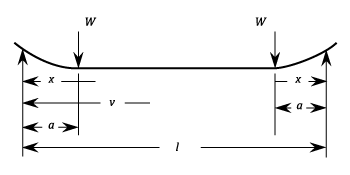
The stress in between each support and the adjacent load:  Stress at the load points and any point between:
  Deflection between each support and the adjacent load:
&space;-&space;x^2]) Deflection between loads:
Deflection between loads: &space;-&space;a^2]) The maximum deflection is at the centre and is:
The maximum deflection is at the centre and is: ) Deflection at the loads is:
Deflection at the loads is: )
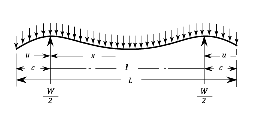
Simply Supported But With Both Ends Overhanging Symmetrically. Uniform Load.

Stress between each support and the end adjacent: ^2) Between the supports:
Between the supports: ) Stress at each support:
Stress at each support:  Stress at the centre:
 }{2\;Z\;L}) The greater of these is maximum stress when the section is constant.
Should
The greater of these is maximum stress when the section is constant.
Should  the stress is zero at points
  on each side of the centre. Should the section be constant and
  ,the stresses at the centre and at the supports are equal and opposite. They are:
 The Deflection between each support and the adjacent end:
&space;-&space;u^2(4c&space;-&space;u)&space;-&space;l^3]) Deflection between the supports
Deflection between the supports
}{24\;E\;I\;L}\;\times[x(l&space;-&space;x)&space;+&space;l^2&space;-&space;6c^2]) Deflection at the ends:
Deflection at the ends: &space;-&space;l^3]) Deflection at the centre:
Deflection at the centre:  When
When  is between
  and
and  the maximum upward deflections occur at points
 }) on each side of the centre. The value of these are :
on each side of the centre. The value of these are :
^2)
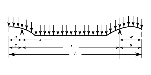
Simply Supported With Both Ends Overhanging, Supports Unsymmetrical, Uniform Load.

Stress for the overhanging length  :
: ^2) Stress between the supports:
Stress between the supports:
&space;+&space;\frac{d^2\;x}{l}\;-x(l&space;-&space;x)\right\}) For the overhang ends of length
For the overhang ends of length  :
: ^2) The stress at the support next to end of length
The stress at the support next to end of length  :
:  The critical stress between the supports is at
  :
:  The value is:
 ) The stress at the support next to end of length
The stress at the support next to end of length  is:
is:  If the cross section is constant, the greatest of these three is the maximum stress.
If
  the stress is zero at points
  on both sides of
  The deflection for the overhanging length
  :
:
&space;+&space;6c^2u&space;-&space;u^2(4c&space;-&space;u)&space;-&space;l^3]) The deflection between the supports:
The deflection between the supports:
}{24\;E\,I\,L}\;\left\{x(l&space;-&space;x)&space;+&space;l^2&space;-&space;2(d^2&space;+&space;c^2)&space;-&space;\frac{2}{l}\;[d^2x&space;+&space;c^2(l&space;-&space;x)]&space;\right\}) The deflection for the overhanging length
The deflection for the overhanging length  :
:
&space;+&space;6d^2w&space;-&space;w^2(4d&space;-&space;w)&space;-&space;l^3]) The deflection at end
The deflection at end  :
: &space;+&space;3c^3&space;-&space;l^3]) The deflection at end
The deflection at end  :
: &space;+&space;3d^3&space;-&space;l^3]) This case is so complicated that conventional general expressions for the critical deflections between the supports can not be obtained.
This case is so complicated that conventional general expressions for the critical deflections between the supports can not be obtained.
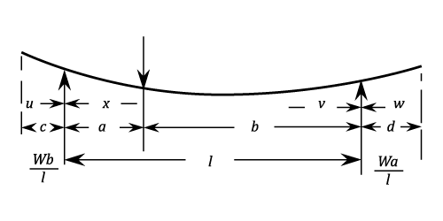
Simply Unsymmetrically Supported With Both Ends Overhanging And A Load At Any Point.

Between the supports for the segment of length 
 For the segment of length
  :
:  Beyond the support
  Stress at the load:
  If the cross section is constant, this is the maximum stress.
Deflection for overhanging length
  :
: ) Deflection for overhanging length
Deflection for overhanging length  :
: ) For the deflection between the supports see paragraph 3 above
Deflection for the end
For the deflection between the supports see paragraph 3 above
Deflection for the end  :
: ) Deflection for the end
Deflection for the end  :
: )
Simply Supported With Ends Overhanging. Single Overhanging Load.

Between load and adjacent support: ) Between supports:
Between supports: ) Between the unloaded end and the adjacent
Between the unloaded end and the adjacent  Stress at the support adjacent to the load:
  If the cross section is Constant, this is the maximum stress. The stress is zero at the other support.
The deflection between the load and the adjacent support
) Deflection between the supports:
Deflection between the supports: (2l&space;-&space;x)) Deflection between the loaded and adjacent support:
Deflection between the loaded and adjacent support:  Deflection at the load:
 ) The Maximum upwards deflection is at
The Maximum upwards deflection is at  and is:
  Deflection at the unloaded end:
 Login
Login


