I have forgotten
my Password

Or login with:

  • Facebookhttp://facebook.com/
  • Googlehttps://www.google.com/accounts/o8/id
  • Yahoohttps://me.yahoo.com

Elastic Foundations

The deflection of beams where the foundations are not rigid.
+ View other versions (4)

Beams On Elastic Foundations.

There are many problems in which a beam is supported on a compressible foundation which exerts a distributive reaction on the Beam of intensity proportional to the compressibility.

In some cases the foundations can only exert upward forces and the beam may, if it is sufficiently long, lose contact with the foundation. In other cases pressure may be exerted either way. Again the support may not be truly continuous( eg. the support of railway lines) but can be replaced by an equivalent distributed support.

If \inline y is the upward deflection of the foundation at any point, then the rate of upward reaction is - \inline ky.

A beam is a horizontal structural element that is capable of withstanding load primarily by resisting bending. The bending force induced into the material of the beam as a result of the external loads, own weight, span and external reactions to these loads is called a bending moment.

Using the theory shown in "Bending of Beams Part 1"

E\;I\;\frac{d^4y}{dx^4}\;= - ky

Or where \inline \alpha ^4 = \displaystyle\frac{k}{4\;E\;I}
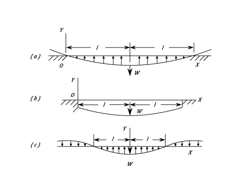
Three standard are now considered:

MISSING IMAGE!

23287/Elastic-Foundation-111.png cannot be found in /users/23287/Elastic-Foundation-111.png. Please contact the submission author.

(a) Long Beam Carrying A Central Load.

Elastic force is a force arising from the deformation of a solid body which depends only on the body's instantaneous deformation and not on its previous history, and which is conservative.

This example assumes that the foundations can only exert an upward force. The length of beam in contact with the foundations is \inline 2l and the Origin \inline O is at the left-hand end.
A solution to \inline \displaystyle \frac{d^4y}{dx^4}\;= - 4\;\alpha ^4\;y can be written as:-

\inline \displaystyle\;y = A\;\sin \alpha x\times \sinh \alpha x + B\;\cos\alpha x\times\sinh\alpha x + C\;\sin\alpha x\times\cosh\alpha x + D\;\cos\alpha x\times\cosh\alpha x

At \inline \;\;\;\;x = 0\;\;\;y = 0\;\;\;\;\;\;\therefore D = 0

And \inline \;\;\;\;\;\;M = E\;I\;\displaystyle\frac{d^2y}{dx^2} = 0\;\;\;\;\;\;\therefore\;\;A = 0

Also \inline \;\;\;\;\;\;F = E\;I\;\displaystyle\frac{d^3y}{dx^3} = 0

Giving:

\inline E\;I\;\times 2\alpha ^3 [B\;(- \cos 0\times \cosh 0 - \sin0\times\sinh0) + C\;(-\sin0\times \sinh0 + \cos0\times\cosh0)] = 0

Thus, \inline C = B

The equation is now reduced to:

y = B\;(\cos\alpha x\times\sinh\alpha x + \sin\alpha x\times\sinh\alpha x)

At \inline x = l\;\;\;\;\;\;\;\displaystyle\frac{dy}{dx} = 0

\therefore\;\;\;\;\;\;\;B\;\alpha \;\cos\alpha l\times\cosh\alpha l = 0

The least solution of this is \inline \displaystyle \alpha l = \frac{\pi }{2} which determines the length in contact with the ground. The value of the constant \inline B is obtained from the condition that the Shear Force at the centre is \inline \displaystyle\frac{W}{2} since by symmetry it must be numerically the same on either side of the load and it must change by an amount \inline W on passing through the load.

Hence,
\frac{W}{2} = E\;I\;\frac{d^3y}{dx^3}\;= - E\;I\times 4\alpha ^3B\;\sin\alpha l\times \sinh\alpha l

Or \inline B = -\displaystyle\frac{W\;\alpha }{2k\;\sinh \displaystyle\frac{1}{4}\pi }

The maximum Deflection and Bending Moment are at the centre, \inline \displaystyle \alpha x = \frac{\pi }{2}

\hat{y}\;= - \left(\frac{W\;\alpha }{2k} \right)\;\coth\;\frac{\pi }{2}

\hat{M} = E\;I\;\left(\frac{W\;\alpha^3 }{k} \right)\;\coth\;\frac{\pi }{2} = \left(\frac{W}{4\alpha } \right)\coth\;\frac{\pi }{2}

Deflection is a term that is used to describe the degree to which a structural element is displaced under a load.

(b) Short Beam Carrying A Central Load W

If \inline \alpha l\;<\;\displaystyle\frac{\pi }{2} in case (a) above, the Beam will sink below the unstressed level of the foundations at all points. Again taking the origin at the left hand end and the overall length of the Beam as \inline 2l, then the following conditions are obtained for the constants of integration of the general solution shown in the previous paragraph.

At \inline \;\;\;\;\;\;x = 0\;\;\;\;\displaystyle\frac{d^2y}{dx^2} = 0\;\;\;\;\;\;\;\therefore\;\;\;\;A = 0

And \inline \;\;\;\;\;x = 0\;\;\;\;\displaystyle\frac{d^3y}{dx^3} = 0\;\;\;\;\;\;\;\therefore\;\;\;\;\;B = C And
y = B(\cos\alpha x\times \sinh\alpha x + \sin\alpha x\times \cosh\alpha x) + D\cos\alpha x\times\cosh\alpha x

At \inline \;\;\;\;\;\;x = l\;\;\;\;\displaystyle\frac{dy}{dx} = 0

\therefore\;\;\;B\times2\cos\alpha l\times \cosh\alpha l + D(- \sin\alpha l\times\cosh\alpha l + \cos\alpha l\times \sinh\alpha l) = 0

And \inline \;\;\;\;\;\;E\;I\;\displaystyle\frac{d^3y}{dx^3} = \displaystyle\frac{W}{2}

Thus

- B\times2\sin\alpha l\times \cosh\alpha l - D(\sin\alpha l\times\cosh\alpha l + \cos\alpha l\times\sinh\alpha l)
= \frac{W}{4E\;I\;\alpha ^3} = \frac{W\;a}{k}

Solving for \inline B and \inline D

B\;= - \frac{W\alpha }{k}\left(\frac{\sin\alpha l\times\cosh\alpha l + \cos\alpha l\times\sinh\alpha l}{\sin2\alpha l + \sinh2\alpha l} \right)

D = -\frac{2W\alpha }{k}\left(\frac{\cos\alpha l\times \cosh \alpha l}{\sin2\alpha l + \sinh\alpha l} \right)

The complete solution for \inline y is now known, the maximum deflection and Bending Moment occur under the load.

(c) An Infinite Beam Carrying A Load.

Assuming that the Support can exert pressure either upwards or downwards and taking the \inline Y axis through the load and the \inline X axis at the undeformed level, a solution to equation (2) can be written in the form:

y = e^{\alpha x}(A\sin\alpha x + B\cos\alpha x) + e^{-\alpha x}(C\sin\alpha x\;+D\cos\alpha x)

For the length to the right of \inline W since \inline \displaystyle y\rightarrow 0 as \inline x\rightarrow \infty \;\;\;\;\;A = B = 0

At \inline \;\;\;\;X = 0\;\;\;\displaystyle\frac{dy}{dx} = 0\;\;\;\;\;\therefore\;\;\;C = D

And \inline \;\;\;\;\;E\;I\;\displaystyle\frac{d^3y}{dx^3}\;= - \displaystyle\frac{W}{2}

Giving \inline \;\;\;\;\;\;C\;= - \displaystyle\frac{W}{8\;\alpha ^3\;E\;I}\;= - \displaystyle\frac{W\;\alpha }{2k}

And \inline \;\;\;\;\;\;y\;\;= - \left( \displaystyle\frac{W\;\alpha }{2k} \right)\;e^{-\alpha x}(\sin\alpha x + \cos\alpha x)

The distance from the load at which \inline y = 0 is given by:

And the least solution is \inline \displaystyle \alpha \;l = \frac{3\;\pi }{4}

The maximum deflection and Bending Moment are at \inline x = 0

\hat{y}\;= - \frac{W\;\alpha }{2\;k}

\hat{M} = E\;I\;\frac{W\;\alpha ^3}{k} = \frac{W}{4\;\alpha }

Example:
[imperial]
Example - Example 1
Problem
A steel railway track is supported on timber sleepers which exert an equivalent load of 400lb./in. length of rail per inch deflection from its unloaded position. For each rail and .

If a point load of 10 tons acts on each rail, find the length of rail over which the sleepers are depressed and the maximum Bending Stress in the rail.
Workings

Each rail can be considered to be an infinitely long beam for which the length over which the downward deflection occurs is given by equation (2)

And the Maximum Bending Moment is given by:

And the maximum Stress is:

Solution
  • The length is
  • The maximum Bending Stress in the rail is